Robotics & Automation Engineering - Juniper Publishers

Abstract
New research in the area of spinning objects has demonstrated a system of the eight inertial torques generated by the rotating masses acts on a gyroscope. The action of this system of interrelated inertial torques manifests all gyroscopic effects. New mathematical models for the inertial torques are used for solving of gyroscopic problems in engineering and presented in several publications. The analytical solution of these publications contains obscurity and vagueness in the mathematical model for the gyroscope precession motion. This model cannot be used for the direct computing of the precession motion. The latter one should be presented by the clear logic and physical principles of the interrelated action of the inertial and external torques. The expression of the precession torque should be presented by a component of the load torque acting on a gyroscope. The novelty of this work is presented by the modified mathematical model for the precession motion of a gyroscope with one side support that enables for the direct computing of the angular velocity. The new model well-matched with practical tests.
Keywords: Gyroscope theory; Precession; Test; Inertial torque
Nomenclature
g – gravity acceleration
e - base of natural logarithm
M –mass of a gyroscopeJ - mass moment of inertia of a rotor’s disc
Jy - mass moment of inertia of a gyroscope around axis y n – ratio of load and precession torque
Tp.x – precession torque acting around axis oy
Tr.x - resulting resistance torque acting around axis ox
t - time
γ - angle of inclination of a rotor’s axle
ω - angular velocity of a rotor
ωi - angular velocity of precession around axis i
Introduction
In engineering, rotating objects are presented by numerous mechanisms that manifest gyroscopic effects in which physics is not well described [1-4]. Gyroscopic effects play an important role in the dynamics of rotating objects and this is the reason textbooks and manuals of engineering mechanics necessarily contain chapters of gyroscope theory [5-9]. Numerous publications dedicated to gyroscopic effects and present different mathematical models for the gyroscope properties [10-13]. Nevertheless, known publications contain simplified analytical models for gyroscopic effects based on the principle of the change in the angular momentum that do not match practical tests [14,15].
Recent investigations of the physical principles of gyroscopic effects demonstrate the action of the system of interrelated inertial torques generated by a rotating mass of spinning objects [16-19]. The new mathematical models for the system of inertial torques produced by rotating mass constitute the fundamental principles of the gyroscope theory. The new publications related to inertial torques acting on gyroscopic devices contain the expression of the precession torque, in which a mathematical model cannot be used for direct computing of the precession motion. The latter is defined by the intermediate equation of the ratio of the angular velocities around two axes. The proposed manuscript presents modified mathematical models for the direct computing of the precession torque and motions around axes for a gyroscope with one side support.
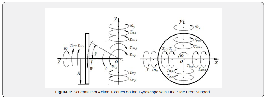
Methodology
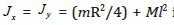
New mathematical models for the system of inertial torques generated by rotating mass and acted on the gyroscope are presented in several publications [16-19]. This system was used to formulate the mathematical models for motions of a gyroscope suspended from the flexible cord [17]. (Figure 1) demonstrates the acting torques on the gyroscope with the free one side support which results in gyroscope motions around axes ox and oy. The modified mathematical models of motions are presented by the following differential equations [17]:
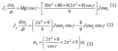
where
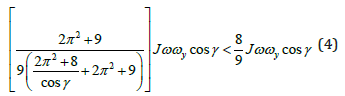
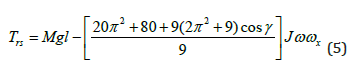
This inequality contradicts to the physical principles of acting torques because the precession torque generates the resistance torque acting around the same axis. The procession torque (Eq. (2) is generated by the action of the resulting torque Trs acting around axis ox that is presented by the right side of Eq. (1):
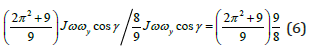
The value of the precession torque should be corrected by the principle of the conservation of the kinetic energy. Since the angular velocity of the gyroscope around axis oy is bigger than around axis ox then the value of the precession torque (Eq. (2)) should be proportionally increased on the ratio of the angular velocities (Eq. (3)) and decreased on the ratio of the precession and resistance torques. This transformation expresses the interdependency of load and inertial torques acting around two axes of the gyroscope motions. The ratio of the precession and resistance torques of Eq. (2) is presented by the following expression:
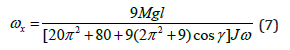
Defined parameters enable the presentation of Eq. (2) by the clear physical principles of acting torques and for the direct computing the angular velocity ω<y of the gyroscope around axis oy. The sign ω<x (Eq. (2)) is replaced by an expression that defined from Eq. (5):
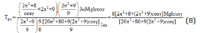
Equation (7) is substituted into an expression of the precession torque (Eq. (2)), increased on the ratio of the angular velocities (Eq. (3)), and decreased on the ratio of the precession and resistance torques (Eq. (6)). Then the modified formula of the precession torque Tp.x is presented by the following expression:
Replacing the precession torque of Eq. (2) by Eq. (8) and transformation yield the equation for the gyroscope’s motion around axis oy:
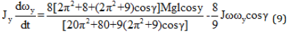
where all components are as specified above. Equation (9) contains the component of the load torque and enables for direct computing of the angular velocity of gyroscope around axis oy.
Case Study
The mathematical model for the motion around axis oy of the gyroscope suspended from the flexible cord is considered for its horizontal location (cos0o = 1.0). All defined technical data and parameters of the gyroscope are used for the case study [17]. Substituting the gyroscope data [17] into Eq. (9) and transformation yields the following expression:

The following solution is the same as presented in [17] which comments are omitted.
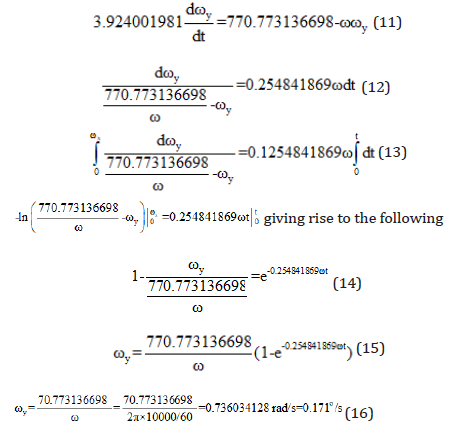
The obtained result is the same as presented in [17] and wellmatched despite some minor differences that can be explained by the accuracy in computing of the parameters for equations. Both equations yield the result of the action of inertial torques generated by the external one. This result is the validation of the correctness of Eq. (9) that can be used for the direct computing of the angular velocity of precession around axis oy.
Results and Discussion
The new analytical study of acting inertial forces on the gyroscope presented by mathematical models of inertial torques and new equations for gyroscope motions around axes. The mathematical model for the gyroscope precession motion does not allow the direct computing of the angular velocity around axis. It can be obtained by the intermediate equation presented by the ratio of the angular velocities around two axes. Practically, it is better to conduct the direct computing of gyroscope precession motion by the modified mathematical model for the precession torque that yields the same result as the known method. The new mathematical model of the precession motion is accepted as correct.
Conclusion
New studies in the area of gyroscope theory generated the new system of mathematical models for the inertial torques and motions of the gyroscope that can raise questions for clarifications. The equation for the gyroscope precession motion cannot be used for computing because contains only expressions of inertial torques. The uncertainties and vagueness in an analytical approach for the precession torque and motion of the gyroscope were resolved. The new model for the precession torque acting on the gyroscope contains the component of the load torque that generates all inertial torques. The modified mathematical model for the precession torque enables for direct computing the angular velocity of the gyroscope motion, clearly describes the physics of acting forces and validated by the practical tests.
To Know more about Robotics & Automation Engineering
Click here: https://juniperpublishers.com/raej/index.php


No comments:
Post a Comment