Material Science - Juniper Publishers
Abstract
In the recent decade, the driving range of pure EVs
with zero emission target has become a popular topic as the massive
battery requirement for longer distance travels means higher vehicle
cost and longer time of recharging periods. Stationary CPT charging
solutions could be an alternative to reduce EVs weight, size and energy
storage unit costs. Fortunately, with progressive success of low-power
CPT charging applications proposed to be commercially produced in the
past decade, hundreds of kilowatts level high-power CPT charging
techniques for EVs are more and more expected to be an optimally
suitable solution for recharging EV batteries, providing higher
propulsion and delivering continuously longer driving range in the next
generations of the EVs. The idea of deploying inductive coupling for EVs
has acquired a lot of attentions in the last decade due to the
contributions and advancements of power electronics, switching power
supply, semiconductors, microprocessors, electrochemistry, material
sciences, control technologies, electromagnetics and so on, despite many
challenges to be addressed including EV manufacturing integration with
CPT system under the chassis, infrastructure difficulties, system
maintenance on both vehicle and transmitting ground sides, actual CPT
performance with real-time coupling on real-world road. In order to
ensure the realization and enhance the sustainability in transportation
sector with the emerging CPT ideas, currently the stationary CPT
charging solutions based on inductive power transfer (IPT) have been
developed from laboratory level as a first step to the practical tests
of commercial realizations. In a few industrial fields nowadays, some of
the proposed CPT technologies with specific coupler coil designs have
been expected for real-world applications. This article presents a state
of the art of the CPT technologies and focuses on reviewing current
coil designs for high-power contactless energy transfer for EVs in the
literature.
Keywords:
Contactless power transfer (CPT); Wireless power transmitting (WPT);
Inductive power transfer (IPT); Coupler; Coil designs; Ferromagnetic
materials; Ferrite cores; Charging efficiency; Power transfer ratings
Introduction
The mainly significant performance parameters and
objectives of a satisfied CPT system are power transfer rating level,
maximum charging distance, system maximum efficiency, charging tolerance
to misalignments, system size and weight. The power level can refer to
how long one full battery recharge would take for a full driving range
of EV. The maximum charging distance determines the vehicle chassis
structure for achieving contactless charging. The system efficiency is
the overall comprehensive parameter of the entire system, which
illustrates how electrically efficiently the CPT phenomenon operates
from AC power supply end to DC battery end for the EV. Charging
tolerance could reveal how the horizontal and longitudinal misalignments
caused by EV drivers’ parking habits impact the actual coupling
charging and power delivered between primary coil and secondary coil,
which also indicates how the flexibility and advantages of CPT systems
are when compared with conventional plug-in charging methods. The
stationary CPT technologies could comprise loosely inductive coupling
and electromagnetic resonant coupling depending
upon different operating frequency range levels and capacitive
compensation adoptions, which are both based on inductive coupling
phenomenon and most of the time are collectively called inductive power
transfer (IPT) in the literature.
Principles of Stationary CPT systems
For the technical background and fundamental
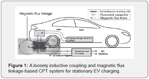
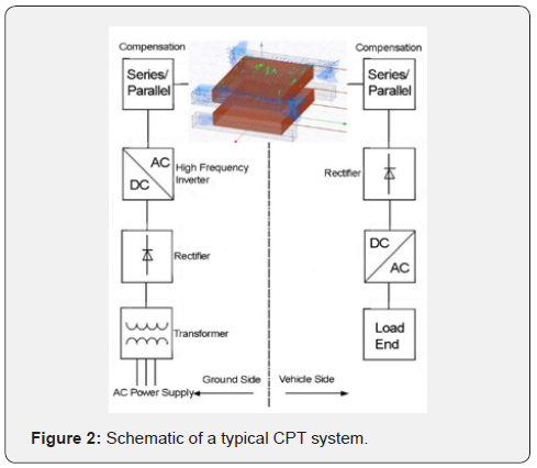
principles of contactless power transfer systems, Figure 1 and Figure 2
illustrate the typical systematic diagram and basics of IPT based
stationary CPT systems. When the IPT charging system is activated by the
signal from EVs reaching over the particular charging platform, the
power supply under pavement will provide 230V AC mains to a transformer
converter which could convert and rectify the high voltage power to
required range of DC voltage. Then, a high frequency (HF) inverter
converts the low frequency DC power to HF AC power. Before being sent to
transmitting pad, the HF AC power is supposed to go through the
compensation module [1] which is considered to optimize the transformer
loss factor. Contactless power transfer coupler transmits the power to
the vehicle side via
effects of magnetic flux linkage namely inductive phenomenon.
After receiving the induced AC power, the compensation circuit
and rectifier/AC-DC converter would operate on the power then
the DC to DC converter of direct conversion method converts the
energy to a required voltage with appropriate low frequencies for
battery energy storage in the end of the whole CPT system. At a
basic level of a real-world CPT system, a power supply requirement
before the coupling module as depicted in Figure 2 is supposed to
include an input rectifier and filtering section, an H bridge inverter
section and current controller if necessary.
History
In 1887, Nikola Tesla invented induction machine that converts
electrical power to mechanical power from a stator to a rotor,
which inspired Tesla again to come up with the idea of wirelessly
transmitting energy via large air gaps based on the principle of
electromagnetic induction machine that was just technically and
commercially proved by himself. In 1901, the concept of wireless
power transmitting (WPT) was firstly proposed and was believed
by Nikola Tesla that it can be used to transfer electricity even far
from America to Europe with an electromagnetics based giant
tower named Wardenclyffe tower in USA, which was terminated
by US government in 1917 and proved that the actual coupling
distance is a huge obstacle to WPT efficiency and effectiveness.
Since then, some experiments were implemented in order to
wirelessly transfer power to a moving train with coupled energy
but still went unsuccessful, which on the other hand proved that
only low-power signal could be transmitted over large distances
such as radio frequency (RF) signals, microwaves, etc. A conclusion
was made at that time that electrical power wirelessly transmitted
is practically impossible from a power point of view throughout
the rest of 19th century [2]. Whilst on the ‘signals’ side, the
sciences over communication systems, non-contacted current
sensors and inductive antennas had been significantly developed
based on Maxwell equations, laws of Ampere’s and Faraday’s and
attempts of Nikola Tesla’s WPT.
With the attempts of powering EVs inductively since 1970s,
stationary CPT topics were re-proposed at the same time. In
1986, Kelly and Owens [3] designed a wireless power transfer
method for a low-power level aircraft entertainment system
with 38 kHz currents going through wires under the carpet
successfully coupling and delivering 8 W power for each passenger
entertainment platform despite very low transfer efficiency.
In 1990, this wireless aircraft entertainment system powering
innovation named ‘regulator for inductively coupled power
distribution system’ was enhanced with a voltage controller and
was patented by Turner and Roth for Boeing aircrafts in the US [4]. In the beginning of 1990s, as academic pioneers, Boys and
Green developed a systematic stationary CPT technology and
patented it in the US [5] with the first definitional names in
this area: inductive power transfer (IPT) or inductively coupled
power transmission (ICPT) system, which includes an elongate
inductor, parallel capacitive compensation, paralleled pickup coils,
decoupling and voltage controllers [6]. This complete IPT system
was modified and improved with enhanced control circuits by
Boys, Covic and Green in 2000, which resulted in an output of up
to 600W with a maximum voltage of 600V at 10 kHz by the system
power supply [7] and, thereby from the power point of view, it was
apparently unable to sufficiently power tens of kilowatts level EVs
or to accomplish hundreds of kilowatts level required fast highpower
battery charging cycles of EVs.
Since 2000, the performances of different stationary CPT
approaches were significantly improved most of the cases in lab
researches rather than industrial level applications. In 2007, MIT
WiTricity project group made a demonstration and claimed that
their wireless power transmission system can lighten a 60-W
bulb over 1 and 2 meters at 9.9 MHz with a transfer efficiency of
between 30% and 90%. This demonstration itself was convincing
but the measured results were unavoidably doubtful when
analysed according to previous studies and experiments over the
past decades in the literature. Nevertheless, the development of
stationary CPT technologies has been facilitated dramatically by
the academic interests and the commercial market requirement
of EVs towards pursuits of zero emission transportation era in the
21st century.
Current status
Among the various previous studies and reports in the
literature, it can be noticed that numerous subtopics have been covered and many breakthroughs have been made towards the
CPT system performance optimization and the commercially
productive realization for EVs. A variety of applications based
on inductive power transfer principle have diversified and the
actual technical challenges have been becoming more noticeable
at the same time, especially for the stationary and dynamic
high power required contactless charging for real-world EVs.
Nonetheless, the inductive coupling-based CPT technologies
and the derived techniques are promising. This section briefly
reviews the developments of stationary charging for EVs over
the past decade and presents the state of the art of stationary
CPT method.
More recently within the past decade, a series of
research institutes, university research groups and industrial
manufacturers have been playing pioneer roles in this field and
making new knowledge contributions from different aspects. Oak
Ridge National Laboratory (ORNL), as a bullet research institute
sponsored by the US Department of Energy in the CPT area, has
carried out some practical experiments empirically resulting in
some analyses and conclusive methods in the national research
centre lab in Tennessee. ORNL focuses on grid-tied high frequency
power inverter, grid side regulation converter, control system and
loosely coupled coil design. Based on the new ultra-thin silicon
IGBT technology, an experimental power inverter and a grid-tied
power converter were designed and tested by ORNL in 2012 [8],
which aims to minimize the mass and size of the coil, rectifier,
filtering, wires, and other components mounted on the secondary
side of vehicle chassis [9].
A 5-kW output inductive stationary CPT system was designed
by a group of the Utah State University, in which an external 37-W
power required FPGA sensors/controller was added to the CPT
system for the dual-side control. Circular coils and LCL converter
were used in this system. Practical experiments in this study were
used to validate the effectiveness of the proposed schematic, by
which the researchers claimed that the system can maintain a
very optimistic efficiency from the grid side to the load in spite
of too many ideally assumed conditions that were made in the
derivative analyses and post-data processing [10]. Nonetheless,
a dual-side control method in this report was proposed to the
inductive coupling system as an innovative way. A researcher of
the University of British Columbia deployed a set of magnetic gears
as transmitting and receiving magnets, an electric motor on the
ground side and a generator on a car chassis to realize a wireless
power transmitting, which is implemented and accomplished
via coupling magnetic gears and driving the generator on the
car to power the vehicle motor. It was claimed that this system
could reach a maximum transmission part efficiency of 81%
with a transferred power of 1.6 kW at a very low frequency of
150 Hz [11]. Regarding the feasibility and realization by gear
coupling and re-generating electricity in a real-world EV charging
application, the proposed system seems to be doubtful in this
study as the additional process of driving the secondary generator
via the magnetic field stored energy for inductively producing the
electricity itself would unavoidably introduce more power losses
eventually contributing to a further reduction of overall system
efficiency ratio.
Two researchers of the Setsunan university in Japan
conducted investigations on several different coil dimensions,
in which it was found that three-dimensional horn-shaped
antennas as transmitting and receiving coils could lead to higher
power transfer efficiency than patch and array antennas whilst
the patch antennas in a nature of planar could be more practical
and suitable for EVs chassis CPT system installation. Thus, the
size and operation performance are to be a trade-off when
considering the entire stationary CPT system from design to
actual fabrication onto EVs. In this study [12] of the University of
Setsunan, the system operating frequency is between 1.2 Ghz and
2.45 GHz, which is in a range of HF. Besides, it is claimed that the
array antennas perform with lower transmission loss than patch
antennas at 2.45 GHz and with a transmission efficiency of over
20% despite of unknown actual power transferred through the
entire system.
A team of Tokyo University contributed numbers of
reports to the field of CPT technologies in the past ten years. Based
on the method conceptualized and named with electromagnetic
resonant coupling by MIT WiTricity in 2007, the research group
of Tokyo University started studying the feasibility and technical
performance of this method with theoretical and practical depth
since 2009. Different from the previous inductive power transfer
(IPT) methods and concepts, the proposed electromagnetic
resonant coupling technology emphasizes on impedance matching
[13] in order for the whole system to approximate to magnetic
resonance, by which predictably the energy transfer efficiency of
the CPT system could be optimized and theoretically the actual
power rating to the load could be very satisfactory.
This group of researchers considered the CPT technology as
small-sized helical antenna transmission topics and pure electrical
equivalence problems [14,15] which led to a convenience of
investigating the system with the antenna scattering parameter
(S-parameter) analysis and the direct experimental methods
of using a vector network analyser (VNA) [16] to measure the
outputs at a usable frequency of the industrial, scientific and
medical (ISM) band-13.56 MHz [17]. Significantly, the impedance
matching theory contributes to the theoretical structure
construction of CPT technologies, especially for the magnetic
resonance accomplishment in this case. Whilst, the over-idealized
impedance matching circuits used in this case neglects the
non-linear magnetic circuit part in the coupling module, which
determines a lot regarding how the actual electromagnetic flux
distribution contributes to the real-time coupling phenomenon
over the air or core based distance with non-linear magnetic
characteristics in nature such as B-H curves and hysteresis effects
in the electromagnetic field. Thus, the absolutely equivalent
circuit method in the case of this research group may be not
sufficiently appropriate and suitable for a CPT system scenario. Besides, working at megahertz level operating frequency and
considering the system as a pure antenna problem especially with
traditional scattering parameter analysis may be not proper as
firstly the real-world CPT systems are not milliwatts level ‘signal
transmission’ topics from power point of view, and secondly the
VNA measurement with a two-port network S-parameter method
may not be adequately applicable any more when it comes to
kilowatts level electrical power issues despite of resonance status.
Nevertheless, the University of Tokyo team did make
contributions towards the knowledge gaps at that time in the
last years of 2000s. With the same methodology, a battery hybrid
energy storage system was also studied by this research group,
by which it is claimed that both the transmission side power
control configuration and the receiving antenna side controller
were designed to achieve satisfactory power charging without
communication units between transmitting and receiving
antennas [18]. However, the Tokyo University research team
turned to study the CPT systems in a loosely coupled frequency
range in the order of kilohertz [19] rather than megahertz
anymore since about 2014. More practically in laboratory and
realistically in applications this time, the researchers mainly
investigated the circuit topologies, transmission coil types, control
methods and capacitor compensations in depth, pointing out that
the effectiveness of magnetic resonance to the wireless power
transfer coupling purpose and proving that the new methodology
contributes more to the system efficiency and power transfer rating
issues [20] with results of 40-90% and 60W, respectively. On the
other side in industry, several technology driven companies and
manufacturers have also been making contributions to the field
of emerging wireless power transfer technologies for stationary
charging from multiple levels and aspects over the past twenty
years, such as WiTricity Corporation, Bombardier, HEVO Power,
Qualcomm Group, Conductix-Wampfler etc.
As mentioned before in the last section, WiTricity as a
corporation was founded by a group of MIT researchers to
investigate and invent wireless energy transmission terminals
for commercial purposes since the first demonstration in 2006.
With the proposed resonance coupling method, WiTricity team
designed a CPT system with tuned coils to wirelessly transfer
power which was claimed with 60 W to 3.3 kW over one meter
at 145-kHz operating frequency [21-24]. Afterwards in 2011,
some other researchers in East Asia carried out resonant coupling
simulations based on WiTricity designs and studies the position
tolerance of the method, by which it was claimed that the simulated
WiTricity model showed a maximum performance at 2.34 MHz
with a coil distance of 50 mm [25]. However, in this report a
real power rating and effectively convincing system efficiency
were not derived and discussed in detail although the peak
values of output voltage magnitudes corresponding to various
coil distances and frequencies were recorded and compared.
Bombardier Transportation company, a leading technology and
solution supplier in Germany, tested their wireless static charging
system called PRIMOVE for buses in 2013. As part of the pure
electric public buses, the PRIMOVE system has been integrated
with improved EV system via this project. Bombardier designed
their own control unit named ‘vehicle detection and segment
control’ (VDSC) and interface called ‘supervisory control and data
acquisition’ (SCADA) subsystems at industrial levels [26], which
seems to be feasible and successful in the real-world application
despite of insufficient technical reports or data released and
published yet. HEVO Power is another technology provider in the US
which aims to innovate a wireless charging system for public
transportations. This company proposed a stationary system
requiring a fixed operating frequency of 85 kHz and targeting at
transferring up to 10-kW power over an air gap of about 30 cm.
It was claimed in 2014 that the receiving side prototype mounted
on the vehicle weighs 11 to 23 kg and that the heating problems
on both the vehicle and ground charging sides can be prevented
by their parking zone design and mobile phone app monitoring
[27]. Qualcomm, a pioneer company dedicated in communication
technologies, informatics and lately emerging wireless power
transmission, has also been implementing research programs
towards an optimal wireless charging equipment for both lowpower
electronic devices and high-power charging applications.Qualcomm Halo is a specific project regarding achieving CPT charging for EVs. Qualcomm aims to realize three options of charging power ratings for future customers in their report in 2013, which are 3.3 kW, 6.6 kW and 20 kW and targets at very high and stable efficiency rate of over 90%. With IPT method, proposed BiPolar and DD coil designs, Qualcomm claimed that their Halo IPT system used 20-kHz operating frequency in the simulation experiments and trial runs of this prototype would be implemented in East London in 2011. It can be noticed that, from the official reports and research report [28] in collaboration with Auckland University, Qualcomm Halo project is very practically profound and technically convincing with strong simulation supports and mathematically theoretical representations by themselves and other researchers [29].
Besides, the double D method has been patented by Qualcomm
years ago from commercial point of view. Conductix-Wampfler,
another technology company in CPT research, is very dedicated
in investigating inductive power transfer (IPT) techniques
and already patented their own IPT trademark in the US. This
company focuses on developing IPT system for automated guided
vehicles (AGV) in warehouse applications with robotics [30,31].
According to their reports until 2018, Conductix-Wampfler aims
to produce the power supply module, charging mat and power
pickup with charging manager unit. Technically, the power supply
AC voltage can be one-phase 100-240V or three-phase 380-480 V
at 50 or 60 Hz, the output power and current can be 1.5 kW and 5
A, respectively. Their power pickup namely receiving coil module with charging manager subsystem aims to inductively receive
about 55 V induced voltage and 10 A current to send to charge a
24-V DC battery with 12-A and 144-W after the power regulation,
DC/DC converter and current monitoring of the charging manager
subsystem. The dimensions of power pickup pad and charging
mat are H 80.3 mm x W 222 mm x D 216 mm and H 7 mm x W 435
mm x D 180 mm, respectively. The aim of the charging distance is
10 mm. It can be seen that Conductix-Wampfler shows not only
respectful ambitions but also technical skills in the industrial
applications for AGV in warehouse systems.
Proposed designs of coupling coils
As the most important part of contactless power transfer
systems with regards to the overall system outputs and
performances, the coupling module design especially the coil
geometry design plays a significant role in order for any types
of CPT architectures from both the power electronics and
electromagnetics perspectives to eventually address the three
main objectives: electrical power transfer ratings of the system;
efficiencies including overall system efficiency to the load end and
coupling part efficiency; CPT air gaps namely charging distances.
Therefore, it is very worthwhile proposing, analysing and
evaluating various coil designs to comprehensively implement the
investigations upon CPT technologies. In this section, the proposed
coil designs in the literature until present are to be enumerated
and briefly analysed.
Circular coils
Until present, from the academic studies to the real-world
commercial applications, the circular coil designs have become
the most common and acceptable approaches for various powerlever
devices such as wireless charging pads for smart phones and
many other portable electronic products. Also, as for the initial
feasibility for high-power level EVs contactless charging, circular
coil with its derivative topologies has been focused and developed
towards the optimizations and some of them are originally
derived from traditional pot cores, according to the reports in the
literature [32-34]. Within the current studies and even commercial
level applications, most of the circular coil designs are coreless
especially for low-power cases [35-37]. As known in transformer
theories and applications, the ferromagnetic cores like ferrite cores
are deployed to prevent excessive energy loss into surrounding
air and materials due to existence of magnetic leakage. And with
the fairly tiny air gap design crossing the core structure instead
of completely enclosed core loop, the core windings can have
minimum disadvantages when effects of proximity occur due to
hysteresis loss and eddy current loss. Similarly and theoretically,
deploying ferromagnetic cores like ferrite in CPT coil designs is
able to constrain magnetic flux lines to expected paths and to
shape the actual electromagnetic field in order to enhance the
effectiveness of coupling, which consequently improves the
wireless energy transfer system performance.
In most small-scale low-power CPT systems for portable
electronic devices like cell phones, wireless charging pads with
coreless coils can acquire more popularity due to pursuits of
relatively thin and lighter design from real-world customers,
certainly under acceptable conditions such as charging power
rating and basic efficiency to be at least satisfied by manufacturers’
efforts on advanced electronic circuitry and control unit designs.
However, high-power CPT applications are more supposed
to need cores to assure the satisfactions of the overall system
performance [38,39], for instance, the circular coil couplers with
solid ferrite pads could form the flux distribution much better. A
design of circular coil with ferrite pad is shown in Figures 3 &4
[10], in which the dimension is in mm. And two coreless circular
coil designs are illustrated in Figures 5&6 for comparisons.
In
addition, the derivatives of circular design have also been depicted
here in Figures 5&6 [40]. In this article, the former design could
be called a design of simplified planar circular coreless coils
and the latter one could be called a design of simplified coreless
solenoid coils, with a categorization nomenclature based on the
characteristics and natures introduced above. The model in Figure
7 could be named a design of circular ring coreless coils, which
illustrates expected magnetic flux lines and distributions in 3D
magnetic simulation. It can be seen that with no ferrite pads or
cores, the flux lines flow through the coils showing more naturally
and smoothly curved paths in air, which can be different from the
circular coils with shaping effects by ferromagnetic materials such
as ferrite pads used on the external sides. 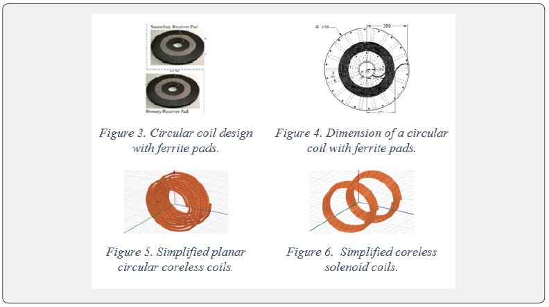

Planar square coils
Geometrically, square windings can take better advantage of
the space under the chassis of vehicles for system installation.
Some reports also have already presented the designs regarding
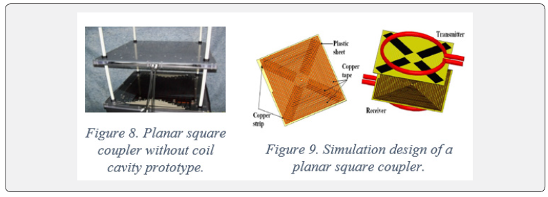
square coils and the derivatives and practically tested. The Oak
Ridge National Laboratory (ORNL) in the US proposed the detailed
designs of their square coupler shown in Figures 8&9 [8,9,41] for
which a category name of ‘planar square coil without a cavity’
can be applied based on the reviewed designs and categorization
nomenclature in this article. The square coils of ORNL are singlelayered
with multiple circles of windings as illustrated and the
winding wires are made of copper. No ferromagnetic materials
are used in this design. Considering different magnetic flux lines
generated and formed by whether or not a cavity exists in the
planar coils, another derivative design can be categorized into
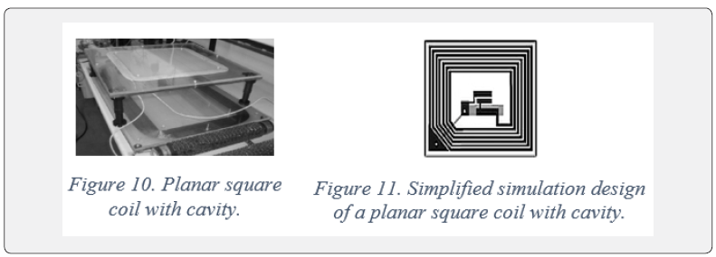
‘planar square coils’ here. Compared with the planar square coil
without a cavity prototype, the model that can be named the
‘planar square coil with a cavity’ has been presented in [42], which
is nearly based on the same dimensional parameters except the
empty cavity design existence within the coils as shown in Figures
10&11.
Solenoidal square coils
When the installation space under a vehicle chassis is not a
major issue, for instance for small-sized automated guided electric
vehicles (AGEV) in warehouse rather than on public traffic road,
a combination design of solenoid coils and square coils can be
proposed, which here is named ‘solenoidal square coil’ despite a
different name in the original report [43]. By a comparison analysis
in this article, it can be explained that, the huge dimensional size
of this kind of design can take advantage of the intracavity space
of the AGEV and theoretically present the optimal performance
of both planar square coil and solenoidal coil due to a larger
internal magnetic flux area and path length as shown in Figure
12. Expectedly, this solenoidal square coil design can improve the
magnetic flux density and eventually enhance the power transfer
efficiency and power rating, which however still needs to be tested
and proved with actual system output performance and feasibility
yet.

Helical solenoid coils
Similar to conventional solenoid structure, the helical solenoid
coil categorized here can be one of the applicable CPT coupler
designs. As shown in Figures 13&14 [44], the helical solenoid
coil design ideally has two coaxial solenoids with horizontal flux
central lines in parallel. With one solenoid as transmitting coil
on the primary side and another solenoid as receiving coil on
the secondary mounted on the vehicle chassis. Figure 14 shows
a cross section of a helical solenoid coil with single-layered
windings. This coil structure theoretically has satisfactory mutual
inductance when two coils have zero misalignment in parallel and
short coupling distance, especially for small electronic devices.
However, this design may have low tolerance to misalignments
which could be a challenge from the EV customer end in realworld
high-power applications if installed on vehicle chassis.
Ferrite cores can be inserted into the cylindrical centre in helical
solenoid coil design for coupling enhancement.

Multilayer helical coils
A novel design called ‘multi-layered helical coil’ is illustrated
in Figures15&16. Theoretically, with numbers of winding turns
and layers, the coil coupling, and mutual inductance will be
increased, consequently enhancing the CPT system performance.
When it comes to high frequency applications like CPT charging
for EVs, the total effects of proximity losses will be significant if
the distance of each turn and layer separation are too close, which
lowers the system efficiency [45]. Thus, this design is not suitable
for high frequency, space tightened and high power required
applications. Further investigations and experimental results
from practical prototypes rather than ideal simulation models are
still required to study this multi-layered helical coil design for the
feasibility and realization of CPT charging of EVs in the future.

Mixed-type coils design
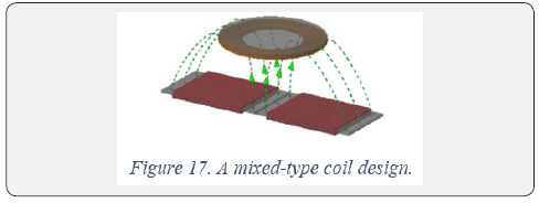
An innovative structure design shown in Figure 17 was
proposed by a team in Japan in 2015. This mixed-typed coil design
[19] is supposed to allow higher tolerance to misalignments,
smaller size and more compact installation for energy receiving
side on EVs as two coaxial square solenoid coils on the transmitting
side are expected to generate stronger magnetic field in order for
the circular receiving coil to capture more amount of magnetic flux
lines. Expectedly, the overall coil magnetic flux distribution of the
CPT system could be boosted when compared with a pure circular
coil design for the same size of chassis of EVs. However, this design
still needs to be further theoretically studied, practically tested
and comprehensively analysed from modelling to experiment due
to few reports in the literature until present.
Double D coils
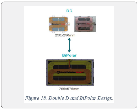
A structure of double D shaped coils was proposed by
Qualcomm Halo program as illustrated in Figure 18. Two coils of
the ideal D shape winded with one long copper wire are on the
ground side as a transmitter, and a polarized receiving coil with
two partially overlapping windings is on the EV chassis side [46].
This DD design was reported to produce higher coupling than
a same-sized circular coil structure [47,48]. However, further
developments about DD coil design and its derivatives are required
by more numerical results and effective system performance.
H-shaped coupler coils
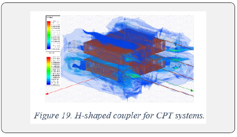
A novel H-shaped coupler with ferromagnetic materials as
cores was proposed in [39,49]. In order to enhance the magnetic
field flux density and CPT coupling performance, different core
materials were tested and analysed. Besides, it was found that the
objectives of CPT systems can be addressed by adding shielding
shells. Especially with aluminium semi-enclosed shielding
shell, the CPT prototype can produce better electromagnetic
characteristics and output more satisfactory system performance
[50], which reflects the effectiveness and feasibility of using
ferromagnetic materials and shielding methods Figure 19.
Asymmetric coils
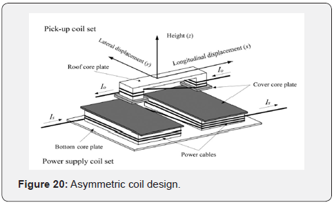
The asymmetric coil structured in Figure 20 was proposed
in 2014 in order to investigate the impact of tolerance to the
stationary CPT system performance. The receiving coil is smaller
than the energy transiting coil set with a purpose of improving
the tolerance of misalignments when parking a vehicle [51].
This structurally innovative coupler design with a transmitting
bottom set size of 200 cm x 100 cm each and a pickup set size
of 16 cm x 16 cm each is claimed to output 15 kW at 20 kHz and
the maximum misalignments can be 40 cm and 20 cm for lateral
and longitudinal axes. This coil design contains ferrite cores as a
ferromagnetic material to facilitate the field. The power supply
is a current source of maximum 100 A in the simulation models.
Nevertheless, further studies about the feasibility for real-world
EVs contactless charging with this type of design are required in
the future, addressing the other major objectives of CPT systems.
Conclusion
In this article, the brief history and basics of CPT systems
using inductive power transfer have been introduced. A series
of both leading research institutes and pioneer industrial
companies worldwide have been listed and discussed in terms
of the development directions, proposed methods and concepts
over CPT technologies. In addition, most of the currently proposed
coupler coil designs have been described and reviewed towards
the major objectives of CPT technologies.


No comments:
Post a Comment